Probe Deskew Tool
This was a quick project to aid my research projects. Oscilloscope probes typically have some measurement delay, but how much is rarely specified. It is relatively consistent between probes of the same model, between models there might be differences of several nanoseconds. This is especially problematic when trying to measure Volts*Amps power in high frequency converters - 10 ns could be a significant portion of the switching period!
Enter the deskew fixture: all it does is generate a simultaneous step in voltage and current, which you can then use to align the timebases of two probes. Most equipment manufacturers sell their own version with some combination of automatic probe adjustment, wide feature set, or impressive stability guarantees, but the price is high. Teledyne’s fully automatic models retail at $1250, while Siglent’s semi-automatic version costs $305. The WEMPEC lab tool went missing in October 2025 so I set out to make my own.
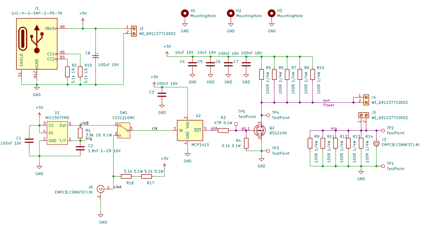
My design is basically a copy of the ones discussed in this EEVblog forum thread, with small alterations for my preferred components. The circuit works as follows:
- A DC supply feeds a current divider with two lower legs with an upper leg of 20 ohms (split into five resistors).
- The driven lower leg is a small MOSFET with only 0.8 nC Qg for maximum switching speed. The MOSFET on-state resistance must be low enough that negligible current flows through the sense leg while it is on.
- The sense leg consists of a wire bridge or coil followed by another 20 ohm resistor bank. The wire can have some (small) inductance, but the resistor bank must have low inductance to supply ground.
- A clock signal drives the MOSFET on and off repeatedly, generating steps of current through the sense leg and voltage across the lower 20 ohm resistor bank.
- Probes measure current in the coil and voltage across the lower resistors, allowing the user to manually adjust for probe skew.
This version generates 125 mA / 2.5 V steps with about 5 ns rise time at a default clock speed of 100 kHz. Such a low current might be problematic for some probes, so multiple wraps of sense wire can artificially raise the measured current while somewhat slowing the rise time.
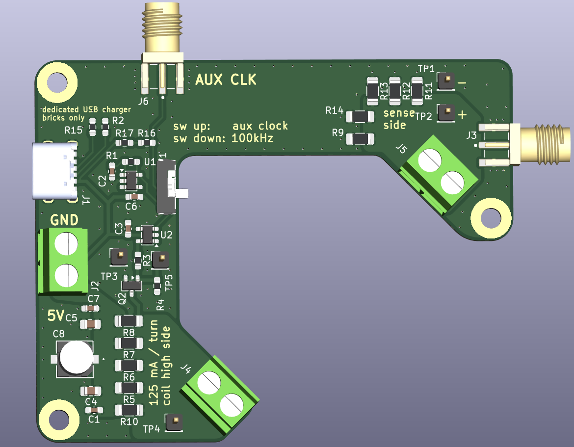
The board cutout is designed to accomodate two standard current probes at once, and the dual terminal blocks allow some flexibility in sense coil winding. My version of the fixture includes an SMA voltage output for direct scope connection as well as an auxiliary clock input should the user desire some frequency beyond what the MIC1557 timer can support. It consumes 1 Watt on average, and care should be taken not to leave the board powered with no clock running, or the top leg resistors may overheat. It can be powered either from a lab bench supply or a USB-C charger, but should not be connected to regular USB peripheral ports.
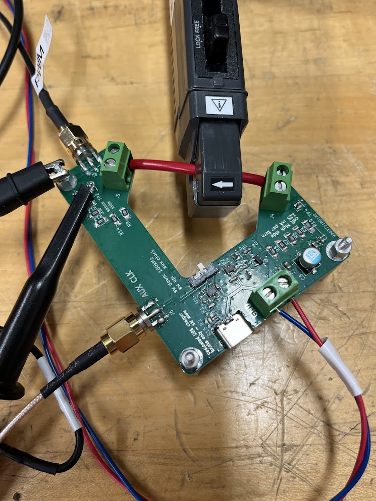
Here it is in action. The left SMA cable brings in an external clock, and the SMA up top is a second voltage sense output directly to the oscilloscope.